Constructing A Face Using Surface Tools

Creating a detailed face using a polygonal modeling tool like 3D-Studio Max has traditionally been very difficult. Until recently, most people doing this kind of work have needed to spend thousands of dollars on 3D digitizing devices. Other 3D packages that allow B-Spline modelling have faired better at the task, but as of release 1.2 MAX users do not have NURBS modelling capability

The tutorials that come with Surface Tools only touch on what is possible with the plugin. This document is designed to supplement the tutorials, not replace them. You should read the tutorials that come with the package before reading this one. You should also be somewhat familiar with MAX in general. This tutorial assumes you have the latest version of Surface Tools, as well as the rewrite of the EditSpline modifier called EditSpline2. EditSpline2 is available on the Spectral Imaging home page in the Surface Tools section.

The first step involved with modelling a face with Surface Tools is gathering reference material. Even if you intend to model a face of your own design, you should use source material. Source material commonly includes hand drawn sketches or photographs. You may also wish to model the object in clay or plaster and then take a picture of it with a digital camera. The reference material will give you a basis for creating splines. Splines make up the structure of the face and provide the framework for which the surface modifier will create the skin. The more views you have for reference, the better off you will be. Mostly you will rely on the front and side view of your face. I used the following reference images when modelling the face above.

These images are photographs of a model created with plaster. The photographs were then scanned into the computer using a mid range quality scanner.


The next step is to create two boxes of suitable height. Make them thin and arrange them perpendicular to each other at their midpoints, as shown in the figure on the right.

Map your reference images onto the boxes. You may need to resize your mapping coordinates or scale your map to match both of the images. You want the various parts of the two images to correspond. In other words, the eye ball socket should be roughly the same height along the Z axis on both of the boxes.

These images will provide you with enough information to begin creating an outline of the face. Since most faces are symmetrical, you will usually only want to model half of the face and then mirror it. If you have an asymetrical face, you will need to model the whole thing, but working with one half at a time is probably a good idea to help you modularize the process.

At this point you will begin tracing the contours of the face. Through this process, you will create a basic framework of splines that intersect each other at common vertex points. Each area of intersection must create either a three or four sided area. The reason that you must create three or four sided areas is that the Surface modifier functions by placing either Tri or Quad patch objects in the areas outlined by the splines. These Patch grids become the surface or skin of your face. You should pay attention to where you place your vertices on your splines. If vertices are placed on a spline and don't serve to connect with another spline to create a three or four sided area, the surface modifier won't function correctly. You will end up with pieces missing from your face where the unattended vertices lie.

You will want to start by creating a line and then changing the vertices to Smooth, Corner, Bezier or Bezier Corner. You will probably want to create a rough outline and then apply EditSpline2 to your line. By modifing individual vertices with EditSpline2, you will fine tune your outlines. One advantage to using EditSpline2 over EditSpline, is that the vertex ticks appear while out of sub-object mode, which helps you visualize where you need to create connecting splines. It is a good idea to start with the major curves which outline the whole face, and fill in detail from there.


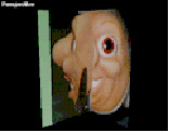
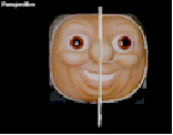
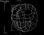
Notice the white splines which surround the outlines of the face images. Once you have these basic outlines, draw lines which follow the contours of the face horizontally. You may wish to create a grid helper object so that you create splines in the rough position in 3D Space where they belong on the face. Then you will go into EditSpline2 and move the vertices forward and back in 3D Space until the spline follows the contour that the face does. This process involves a little artistic judgement. Use your referrence images and your own judgement to adjust the splines. One trick that Peter Watje recommends for beginners is to load a head mesh and use that as a reference. You can find head meshes 3D Café and Avalon. You will also need to adjust the Bezier tangents. For example, in the front viewport draw a line that follows the contour of the face from the nose over the eye brow and back to the end of the face. Then use a combination of the Top, Side and User views to manipulate the vertices until they create a contour line. The curve in figure 1.9 traces the contour of the face starting at the nose and following along the nose to the eye where it curves over the eye and finishes at the end of the face.


At the end points of the new spline there should be a corresponding vertex point on both the side and front splines. The end vertices of the new spline, and the vertex points on the side and front splines should be adjacent to each other in 3D space. At this point you can attach the splines together so that you only have one object. Using EditSpline2, you can now select and weld the coincident vertices on both the side and front splines of the head. Figure 1.9 illustrates where these points are. This is another reason to use EditSpline2, for it allows you to weld together any number of vertices. The Surface modifier will work even if the vertices are not welded together, but it is better to have one seemless object.

Repeat this process with the rest of the horizontal curves of the face, starting with the front viewport and then using a combination of views to arange the vertices and their tangents so that the splines follow the curvatures of the face. Welding the vertices should make it easier to manipulate the entire structure. You will probably need to increase the weld threshold to get vertices to weld.

Figure 2.0 shows the spline structure with all of the horizontal splines in place. You can see that the basic outline of the face is starting to take shape. At this point, you will begin creating your vertical splines. Remember that you want your splines to outline three or four sided areas so that the surface modifier will function properly. You may wish to hide the boxes at this point as well so that you can move around your geometry in the viewports without obstruction.

The figures above show the face after the vertical splines have been drawn. Notice that all areas defined by the splines have either three or four sides. Also notice that all the vertices serve to connect splines. In other words, vertices are not used to shape the splines, the tangents are. Once you have your face arranged in this manner, you can mirror the object.
At this point you should attached the two sides together and weld the coincident vertices in the middle. You now should have a skeleton that you can apply the surface modifier to.


For this particular face I wanted a loose skin look, so after I applied the surface modifier I added a Relax modifier which helped smooth the whole object out.


Finally, add mapping coordinates and create a texture map for the face. The best way I have found to create a detailed texture map for the face is to use Peter Watje's unwrap utility to create a bitmap representing where the texture lies on the object. Then go into Fractal Painter and paint the face over the image that Unwrap creates.


The result is a 3D model surprisingly faithful to the original reference material.

Written by Adam Silverthorne Morgan 3D